Suffix code
| Model |
Code |
Information |
| GR200 - |
 |
|
|
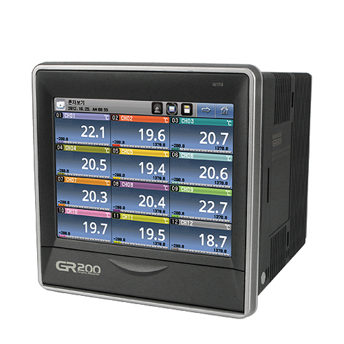
Graphic recorder 145(W) x 145(H) x 173.5(D) ㎜ |
| Number of channels |
2 |
|
|
2 channel |
| 4 |
|
|
4 channel |
| 8 |
|
|
8 channel |
| 12 |
|
|
12 channel |
External contact
input & output
(DI / DO) |
N |
|
None |
| 1 |
|
DI 2 contact + DO 6 contact (relay) |
| 2 |
|
DI 4 contact + DO 12 contact (relay) |
| Communication |
0 |
RS422/485 |
| ※ Ethernet is available when using our ethernet converter(HMCE). |
Specification
| [ Range configuration for the input types ] |
| Input type |
Measurement range(°C) |
Measurement range(°F) |
Degree |
| Thermoresistor (RTD) |
Pt100Ω |
Pt-0 |
-200 ~ 640 |
-300 ~ 1180 |
±0.15 % of F.S ±1digit |
| Pt-1 |
-1 -200.0 ~ 640.0 |
-300.0 ~ 1180.0 |
| Pt-2 |
-200.00 ~ 640.00 |
-300.0 ~ 1180.0 |
| KPt100Ω |
KPt-0 |
-200 ~ 500 |
-300 ~ 1000 |
| KPt-1 |
-200.0 ~ 500.0 |
-300.0 ~ 1000.0 |
| KPt-2 |
-100.00 ~ 150.00 |
-300.0 ~ 1000.0 |
| Thermocouple (TC) |
K |
K-0 |
-200 ~ 1370 |
-300 ~ 2500 |
±0.15 % of F.S ±1digit |
| K-1 |
-200.0 ~ 1370.0 |
-300 ~ 2500 |
±0.15 % of F.S ±1digit(*2) |
| J |
-200.0 ~ 1200.0 |
-300 ~ 2300 |
±0.15 % of F.S ±1digit(*2) |
| E |
-200.0 ~ 1000.0 |
-300 ~ 1800 |
±0.15 % of F.S ±1digit(*2) |
| T |
-200.0 ~ 400.0 |
-300 ~ 750 |
±0.15 % of F.S ±1digit(*3) |
| R |
0.0 ~ 1700.0 |
0 ~ 3100 |
±0.15 % of F.S ±1digit(*4) |
| B |
0.0 ~ 1800.0 |
0 ~ 3300 |
±0.15 % of F.S ±1digit (*1) |
| S |
0.0 - 1700.0 |
0 ~ 3100 |
±0.15 % of F.S ±1digit(*4) |
| L |
-200.0 ~ 900.0 |
-300 ~ 1300 |
±0.15 % of F.S ±1digit(*2) |
| N |
-200.0 ~ 1300.0 |
-300 ~ 2400 |
±0.15 % of F.S ±1digit(*3) |
| U |
-200.0 ~ 400.0 |
-300 ~ 750 |
±0.15 % of F.S ±1digit(*3) |
| Wre 5-26 |
0.0 ~ 2300.0 |
0 ~ 4200 |
±0.15 % of F.S ±1digit(*4) |
| PL-Ⅱ |
0.0 ~ 1390.0 |
0 ~ 2500 |
±0.15 % of F.S ±1digit |
| VDC |
-10 - 20 ㎷ |
-10.00 ~ 20.00 |
±0.15 % of F.S ±1digit
* The current input (4~20㎃ DC)
is available when you use resistance 250Ω (0.5W/0.1%)
on input terminals |
| 0 - 100 ㎷ |
0.00 ~ 100.00 |
| 1 - 5 V |
1.00 ~ 5.00 |
| 0 - 30 V |
0.00 ~ 30.00 |
| (*1) 0 ~ 400℃ : ±5% of F.S ± 1digit |
(*3) -200 ~ -150℃ : ±0.4% of F.S ± 1digit |
| (*2) -200 ~ -150℃ : ±0.2% of F.S ± 1digit |
-150 ~ -100℃ : ±0.2% of F.S ± 1digit |
| |
(*4) 0 ~ 200℃ : ±0.2% of F.S ± 1digit |
| [ Specification for the input ] |
| VDC |
Thermocouple (TC) |
K, J, E, T, R, S, B, N |
IEC 584 |
| PL-Ⅱ, Wre 5-26 |
ASTM E988 |
| U, L |
DIN 43710, IEC 751 |
| Thermoresistor (RTD) |
Pt100 Ω |
DIN IEC 751 |
| KPt100 Ω |
JIS C1604-1989 (OLD) |
| Power voltage |
100 - 240 V AC Voltage fluctuation rate ±10 % |
| Power frequency |
50 - 60 ㎐ |
| Power consumption |
22 VA max |
| Maximum internal fuse ratings |
250 V AC |
| Internal voltage |
Primary terminal* and secondary terminal** : Minimum 1500 VAC for 1 minute
Primary terminal* and FG terminal : Minimum 1500 VAC for 1 minute
Secondary terminal** and FG terminal : Minimum 1500 VAC for 1 minute
Secondary terminal** and secondary terminal** : Minimum 500 VAC for 1 minute
* Primary terminal : Power terminal (except the FG terminal) and the relay output terminal
** Secondary terminal : Sensor input terminal, contact input terminal, communication terminal |
| Insulation resistor |
20 ㏁ between the power terminal and the FG terminal or 500 VDC |
| Number of channels |
2, 4, 8, 12 (Refer to the type configuration) |
| Input type |
2 thermoresistors (Pt-100, KPt-100) 12 thermocouples (K, J, E, T, R, B, S, L, N, U, Wre 5-26, PL-II) 4 VDC (-10 - 20 mV, 0 - 100 mV, 1 - 5V, 0 - 30 V) |
| Sampling period |
250 ㎳ |
| Current to measure the thermoresistor (RTD) |
About 0.21 ㎃ |
| Input resistor |
Thermocouple : More than 1 ㏁, VDC : More than 1 ㏁ |
| Allowable wiring resistor |
Thermoresistor : Maximum 100Ω/wire (The RTD is up to 10Ω/wire for the range of -100.00 - .150.00) Thermocouple : Less than 200 Ω VDC : Less than 2 ㏀ |
| Impact of the wiring resistor |
Thermoresistor : ±0.3 °C/10 Ω (The 3 lines have the same wiring resistors) |
| Allowable input voltage |
Thermocouple : Less than ±10 V DC, VDC : Less than ±33 V DC |
| Degree |
±0.15 % of F.S, ±1 digit (Except the RJC temperature error) ※ Refer to the input table |
| The error in the reference junction compensation (RJC) |
±2.0 ℃ (0 ~ 50 ℃) |
| Sensor short detection (Burn-out) |
UP-Scale for the short |
| Maximum input |
4 |
| Input method |
No voltage contact input |
| On/Off detection resistor |
Consider on less than 1 ㏀ minimum and off larger than 10 ㏀ |
| Minimum detection time |
0.25 second |
| Maximum number of outputs |
12 |
| Output type |
Relay output |
| Maximum ratings |
5 A 250 V AC, 5 A 30 V DC |
| Recommended ratings |
3 A 250 V AC, 3 A 30 V DC |
| Relay life |
50,000 times at the maximum ratings, 100,000 times at the recommended ratings |
| Display |
TFT color LCD
(115.2 × 86.4 ㎜, resolution : 640 × 480 pixel, LED Backlight) |
| Backlight life |
40,000 hours |
Language in use |
Korean, English, Chinese (simplified) |
| Save function |
Internal memory - volatile memory : 900 KB - Save up to 4 hours with the interval of 1 second - Non-volatile memory : 80 MB . Save up to 15 days with the interval of 1 second External memory - SD card (2GB) : Save up to a year with the interval of 1 second ※ Support the SDHC |
| Save period |
User configuration (1, 2, 5, 10, 20, 30, 60, 120 seconds) |
| Memory information |
Measurement from each channel, Burn-out, DI (contact input), ALARM, relay output status |
| Ambient temperature |
0 ~ 50 °C |
| Temperature change |
10 °C/h or below |
| Ambient humidity |
20 ~ 90 % RH (no condensation) |
| Ambient temperature |
-20 ~ 70 °C |
| Temperature change |
Less than 20 °C/h |
| Ambient humidity |
5 - 95 % RH (no condensation) |
| [Impact from the ambient temperature] |
| VDC, thermocouple sensor |
±0.01 % of F.S / °C |
| Thermoresistor sensor |
±0.06 °C/°C |
|