Servo MITSUBISHI J3 DRIVE
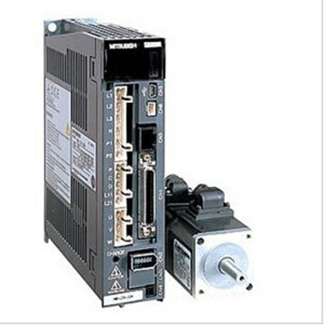
MR-J3 servo family is a high functional, high performance, and easy to use product that offers a wide variety of options to improve total system dynamics, machine performance providing a high performance servo system that is ideal for a wide variety of applications.
Amplifier Types
Type |
Interface |
Control Mode |
Setup Software |
||||||||||||
Pulse Train |
Analog |
DIO |
SSCNET III |
RS-422 |
CC-Link |
EtherCAT (*4) |
Position |
Speed |
Torque |
Position Functions |
Fully Closed Loop Control |
Turret Index |
|||
A-Type |
General Purpose Interface |
x |
x |
- |
- |
x |
- |
x |
x |
x |
x |
- |
- |
x |
x |
B Safety Type |
Advanced High-Speed Serial Bus SSCNETIII |
- |
- |
- |
x |
- |
- |
- |
x |
x |
x |
- |
x |
- |
x |
B Dual Axis |
|
- |
- |
- |
x |
- |
- |
- |
x |
x |
x |
- |
- |
- |
x |
T-Type |
Built-in CC-Link Positioning Function |
x (*2) |
- |
x (*3) |
- |
x |
x |
- |
x |
- |
- |
x |
- |
- |
x |
Type |
Model |
Power |
Source Capacity (*1) |
Compatible Motor Series |
||||||||
HF-KP |
HF-MP |
HF-SP |
HF-JP |
HC-LP |
HC-RP |
HC-UP |
HA-LP |
|||||
A-Type |
General Purpose Interface |
MR-J3_A |
3-Phase 200VAC |
0.05 ~ 37kW |
x |
x |
x |
x |
x |
x |
x |
x |
MR-J3-_A1 |
1-Phase 100VAC |
0.05 ~ 0.4kW |
x |
x |
- |
- |
- |
- |
- |
- |
||
MR-J3-_A4 |
3-Phase 400VAC |
0.5 ~ 55kW |
- |
- |
x |
x |
- |
- |
- |
x |
||
B Safety Type |
Advanced High-Speed Serial Bus SSCNETIII |
MR-J3-_BS |
3-Phase 200VAC |
0.05 ~ 37kW |
x |
x |
x |
x |
x |
x |
x |
x |
MR-J3-_BS1 |
1-Phase 100VAC |
0.05 ~ 0.4kW |
x |
x |
- |
- |
- |
- |
- |
- |
||
MR-J3-_BS4 |
3-Phase 400VAC |
0.5 ~ 55kW |
- |
- |
x |
x |
- |
- |
- |
x |
||
B Dual Axis |
|
MR-J3W-_B |
3-Phase 200VAC |
0.05 ~ 0.75kW |
x |
x |
- |
- |
- |
- |
- |
- |
T-Type |
Built-in CC-Link Positioning Function |
MR-J3-_T |
3-Phase 200VAC |
0.05 ~ 25kW |
x |
x |
x |
x |
x |
x |
x |
x |
MR-J3-_T1 |
1-Phase 100VAC |
0.05 ~ 0.4kW |
x |
x |
- |
- |
- |
- |
- |
- |
||
MR-J3-_T4 |
3-Phase 400VAC |
0.5 ~ 22kW |
- |
- |
x |
x |
- |
- |
- |
x |
||
Notes:
1. Capacity selection software MSIZE (MRZJW3-MOTSZ111) can be downloaded for free from www.meau.com.
2. Please use the manual pulse generator (MR-HDP01).
3. Please use the extended IO unit (MR-D01).
4. Please use the interface module MR-J3-T04.
100V/200V Amplifier Selection: (Example Part No. = MR-J3-10BS)

Notes:
1. Converter Unit MR-J3-CR55K is required for 30kW and 37kW amplifiers.
2. Available for MR-J3-A and B Safety types only.
3. Use this servomotor with a dedicated servo amplifier MR-J3-_A(4)/BS(4)/T(4)-U1_ _ when increasing the maximum torque.
4. These motors can be used by setting parameter No. Po04 to “_ _1_”.
5. These motors are not compatible with FX3U-20SSC-H controller.
6. Use a dedicated servo amplifier MR-J3-_A(4)/BS(4)/T(4)-LR/-LW for HF-JP11K1M(4) and HF-JP15K1M(4). These servomotors cannot be used with any other servo amplifiers without “-LR”.
400V Amplifier Selection: (Example Part No. = MR-J3-60A4)

Notes:
1. Converter Unit MR-J3-CR55K4 is required for 30kW to 55kW amplifiers.
2. Available for the MR-J3-A and B Safety types only.
3. These motors can be used by setting parameter No. Po04 to “_ _1_”.
4. Use a dedicated servo amplifier MR-J3-_A(4)/BS(4)/T(4)-LR/-LW for HF-JP11K1M(4) and HF-JP15K1M(4).
These servomotors cannot be used with any other servo amplifiers without “-LR”.
MR-J3-A Servo Amplifier Specifications 100/200V 22kW or Smaller
Servo Amplifier Model MR-J3- |
10A |
20A |
40A |
60A |
70A |
100A |
200AN |
350A |
500A |
700A |
11KA |
15KA |
22KA |
10A1 |
20A1 |
40A1 |
|
Stocked Item |
S |
S |
S |
S |
S |
S |
S |
S |
S |
S |
S |
- |
- |
S |
S |
S |
|
Main Circuit Power Supply |
Voltage/Frequency (*1, *2) |
3-phase 200 to 230VAC 50/60Hz or 1-phase 200 to 230VAC 50/60Hz (*10) |
3-phase 200 to 230VAC 50/60Hz |
1-phase 100 to 120VAC 50/60Hz |
|||||||||||||
Permissible Voltage Fluctuation |
For 3-phase 200 to 230VAC: 3-phase 170 to 253VAC |
3-phase 170 to 253VAC |
1-phase 85 to 132VAC |
||||||||||||||
Permissible Frequency Fluctuation |
±5% maximum |
||||||||||||||||
Control Circuit Power Supply |
Voltage/Frequency |
1-phase 200 to 230VAC 50/60Hz (*10) |
1-phase 200 to 230VAC 50/60Hz |
1-phase 100 to 120VAC 50/60Hz |
|||||||||||||
Permissible Voltage Fluctuation |
1-phase 170 to 253VAC |
1-phase 85 to 132VAC |
|||||||||||||||
Permissible Frequency Fluctuation |
±5% maximum |
||||||||||||||||
Power Consumption (W) |
30 |
45 |
30 |
||||||||||||||
Interface Power Supply |
24VDC ±10% (required current capacity: 300mA (*7)) |
||||||||||||||||
Regenerative Resistor/ Tolerable Regenerative Power (W) (*3, *4) |
Built-in Regenerative Resistor |
- |
10 |
10 |
10 |
20 |
20 |
100 |
100 |
130 |
170 |
- |
- |
- |
- |
10 |
10 |
External Regenerative Resistor (Standard Accessory) (*5, *6) |
- |
- |
- |
- |
- |
- |
- |
- |
- |
- |
500 (800) |
850 (1300) |
850 (1300) |
- |
- |
- |
|
Control System |
Sine-wave PWM control/current control system |
||||||||||||||||
Dynamic Brake |
Built-in (*8, *13) |
External option |
Built-in (*8, *13) |
||||||||||||||
Safety Features |
Overcurrent shutdown, regeneration overvoltage shutdown, overload shutdown (electronic thermal), servomotor overheat protection, encoder fault protection, regeneration fault protection, undervoltage/sudden power outage protection, overspeed protection, excess error protection |
||||||||||||||||
Position Control Mode |
Maximum Input Pulse Frequency |
1Mpps (when using differential receiver), 200kpps (when using open collector), (4Mpps) (*11) |
|||||||||||||||
Positioning Feedback Pulse |
Resolution per encoder/servomotor rotation: 262144 p/rev |
||||||||||||||||
Command Pulse Multiple |
Electronic gear A/B multiple, A: 1 to 1048576, B: 1 to 1048576, 1/10 < A/B < 2000 |
||||||||||||||||
Positioning Complete Width Setting |
0 to ±10000 pulses (command pulse unit) |
||||||||||||||||
Excess Error |
±3 rotations |
||||||||||||||||
Torque Limit |
Set by parameters or external analog input (0 to +10VDC/maximum torque) |
||||||||||||||||
Speed Control Mode |
Speed Control Range |
Analog speed command 1:2000, internal speed command 1:5000 |
|||||||||||||||
Analog Speed Command Input |
0 to ±10VDC/rated speed (possible to change the speed in 10V using the parameter No. PC12.) (*12) |
||||||||||||||||
Speed Fluctuation Rate |
±0.01% maximum (load fluctuation 0 to 100%) 0% (power fluctuation ±10%) ±0.2% maximum (ambient temperature 25°C±10°C (59°F to 95°F)), when using analog speed command |
||||||||||||||||
Torque Limit |
Set by parameters or external analog input (0 to +10VDC/maximum torque) (*12) |
||||||||||||||||
Torque Control Mode |
Analog Torque Command Input |
0 to ±8VDC/maximum torque (input impedance 10 to 12kΩ) (*12) |
|||||||||||||||
Speed Limit |
Set by parameters or external analog input (0 to ±10VDC/rated speed) |
||||||||||||||||
Structure |
Self-cooling open (IP00) |
Fan cooling open (IP00) |
Self-cooling open (IP00) |
||||||||||||||
Environment |
Ambient Temperature |
0 to 55°C (32 to 131°F) (non-freezing), storage: -20 to 65°C (-4 to 149°F) (non-freezing) |
|||||||||||||||
Ambient Humidity |
90% RH maximum (non-condensing), storage: 90% RH maximum (non-condensing) |
||||||||||||||||
Atmosphere |
Indoors (no direct sunlight); no corrosive gas, inflammable gas, oil mist or dust |
||||||||||||||||
Elevation |
1000m or less above sea level |
||||||||||||||||
Vibration |
5.9m/s² maximum |
||||||||||||||||
Weight kg (lb) |
0.8 (1.8) |
0.8 (1.8) |
1.0 (2.2) |
1.0 (2.2) |
1.4 (3.1) |
1.4 (3.1) |
2.1 (4.6) |
2.3 (5.1) |
4.6 (10) |
6.2 (14) |
18 (40) |
18 (40) |
19 (42) |
0.8 (1.8) |
0.8 (1.8) |
1.0 (2.2) |
|
Notes:
1. Rated output and speed of a servomotor are applicable when the servo amplifier, combined with the servomotor, is operated within the specified power supply voltage and frequency. Torque drops when the power supply voltage is below the specified value.
2. For torque characteristics when combined with a servomotor, refer to the section “Servomotor torque characteristics” in this catalog.
3. Optimal regenerative resistor varies for each system. Select the most suitable regenerative resistor by using the capacity selection software.
4. Refer to the section “Options • Optional regeneration unit” in this catalog for the tolerable regenerative power (W).
5. The servo amplifier (MR-J3-_KA-PX) without an enclosed regenerative resistor is also available.
6. The value in ( ) applies when the external regenerative resistors, GRZG400-_Ω, (standard accessory) are used with cooling fans (2 units of 92 x 92mm, minimum air flow: 1.0m³/min). Note that change in the parameter No. PA02 is required.
7. 300mA is the value when all of the input/output points are used. The current capacity can be stepped down according to the number of input/output points in use. Refer to “MR-J3-_A SERVO AMPLIFIER INSTRUCTION MANUAL” for details.
8. Special specification models without a dynamic brake, MR-J3-_A -ED and MR-J3-_A1-ED, are also available for 7kW or smaller servo amplifier.
9. The MR-J3-350A or smaller servo amplifier can be installed close together. In this case, keep the ambient temperature within 0 to 45°C (32 to 113°F), or use the servo amplifier with 75% or less of the effective load rate.
10. The special specification model, MR-J3-_A-U004, is also available for 1-phase 200 to 240 VAC.
11. 4Mpps compatible servo amplifier (MR-J3-_A(1)-KE) is also available.
12. High resolution analog speed command and analog torque command is available with a set of MR-J3-_A(1)-RJ040 and the extension IO unit, MR-D01.
13. When using the built-in dynamic brake, refer to “MR-J3-_A SERVO AMPLIFIER INSTRUCTION MANUAL” for the permissible load inertia moment ratio.
Servo MITSUBISHI J3 MOTOR
200V Motor Selection: (Example Part# = HF-SP102BK)
Not all options are available for every motor.