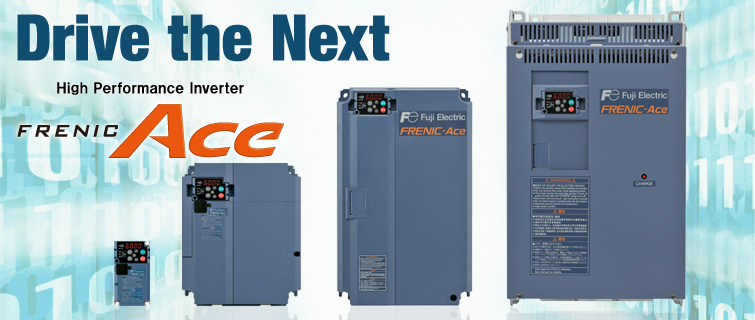
Inverter FUJI ACE (FRN-E2S)

Customizable logic function is available as a standard feature. FRENIC-Ace has built-in customizable logic functions with a maximum of 200 steps including both digital and analog operation functions, giving customers the ability to customize their inverters—from simple logic functions to full-scale programming. Fuji Electric also has plans to offer programming templates for wire drawing machines, hoists, spinning machines, and other applications so that the FRENIC-Ace can be used as a dedicated purpose inverter.
How To Read The Model Number

FRENIC-Ace has readily available interface cards and various types of fieldbus / network to maximize its flexibility.
| Option | Installation type |
|---|---|
| RS485 communications card PG interface (5V) card PG interface (12/15V) card |
 |
| DeviceNet communication card CC-Link communication card PROFIBUS-DP communication card (Coming Soon) EtherNet/IP communication card (Coming Soon) ProfiNet-RT communication card (Coming Soon) CANopen communication card (Coming Soon) Digital input/output interface card Analog input/output interface card |
 |
Spectifications
Three phase 400V class series

| *1 | Fuji 4-pole standard motor | ||||||
| *2 | Rated capacity is calculated by assuming the output rated voltage as 440 V. | ||||||
| *3 | Output voltage cannot exceed the power supply voltage. | ||||||
| *4 | When the carrier frequency (F26) is set to below value or higher, the inverter is sure to be necessary to derate their nominal current.
|
||||||
| *5 | The value is calculated assuming that the inverter is connected with a power supply with the capacity of 500 kVA (or 10 times the inverter capacity if the inverter capacity exceeds 50 kVA) and %X is 5%. Be sure to use the DCR when applicable motor capacity is 75kW or above. |
||||||
| *6 | Obtained when a DC reactor (DCR) is used. | ||||||
| *7 | Average braking torque for the motor running alone. (It varies with the efficiency of the motor.) | ||||||
| *8 | Voltage unbalance (%) =(Max. voltage (V) - Min. voltage (V))/Three -phase average voltage (V) × 67 (IEC 61800 - 3) If this value is 2 to 3%, use an optional AC reactor (ACR). | ||||||
| *9 | The EMC Filter Built-in Type supports only a product for EU. | ||||||
| *10 | ■: S: Standard (basic type), E: EMC filter built-in type (0059 to 0590) | ||||||
| *11 | HND spec. of the type 0007 and 0012: allowable ambient temperature 40 °C (+104 °F) or less. The rated output current at HND spec. is decreased 1% for every 1 °C (1.8 °F) when ambient temperature is +40 °C (+104 °F) or more. |
||||||
| *12 | ●: A: 1 CAN terminal, 1 analog current output B: NONE CAN terminal, 2 analog current output |

| *1 | Fuji 4-pole standard motor | ||||||
| *2 | Rated capacity is calculated by assuming the output rated voltage as 440 V. | ||||||
| *3 | Output voltage cannot exceed the power supply voltage. | ||||||
| *4 | When the carrier frequency (F26) is set to below value or higher, the inverter is sure to be necessary to derate their nominal current.
|
||||||
| *5 | The value is calculated assuming that the inverter is connected with a power supply with the capacity of 500 kVA (or 10 times the inverter capacity if the inverter capacity exceeds 50 kVA) and %X is 5%. Be sure to use the DCR when applicable motor capacity is 75kW or above. |
||||||
| *6 | Obtained when a DC reactor (DCR) is used. | ||||||
| *7 | Average braking torque for the motor running alone. (It varies with the efficiency of the motor.) | ||||||
| *8 | Voltage unbalance (%) =(Max. voltage (V) - Min. voltage (V))/Three -phase average voltage (V) × 67 (IEC 61800 - 3) If this value is 2 to 3%, use an optional AC reactor (ACR). | ||||||
| *9 | The 400 V class series with type 0203 or above is equipped with a set of switching connectors (male) which should be configured according to the power source voltage and frequency. | ||||||
| *10 | The EMC Filter Built-in Type supports only a product for EU. | ||||||
| *11 | ■: S: Standard (basic type), E: EMC filter built-in type (0059 to 0590) |


